-
1 co-ordination
- координация (контакторов и пускателей) с устройствами защиты от короткого замыкания
координация (контакторов и пускателей) с устройствами защиты от короткого замыкания
-7.2.5 Координация с аппаратами защиты от коротких замыканий
7.2.5.1 Работоспособность в условиях короткого замыкания (номинальный условный ток короткого замыкания)
... Допускается координация двух типов — 1 или 2....
Координация типа 1 требует, чтобы в условиях короткого замыкания контактор или пускатель не создавали опасности для людей или оборудования, хотя они могут оказаться непригодными для дальнейшей эксплуатации без ремонта и замены частей.
Координация типа 2 требует, чтобы в условиях короткого замыкания контактор или пускатель не создавали опасности для людей или оборудования и оставались пригодными для дальнейшей эксплуатации. Возможность сваривания контактов допускается, и в этом случае изготовитель должен рекомендовать меры по обслуживанию аппаратов.
[ ГОСТ Р 50030.4.1-2002 (МЭК 60947-4-1-2000)]Параллельные тексты EN-RU
Co-ordination type 1 and type 2
The co-ordination typologies admitted by the Standard with reference to the behavior of the protection device against short-circuit towards the starter components are classified as “type 1” and “type 2”.
Under short-circuit conditions, the coordination of type “1” allows the contactor and the overload relay to be damaged; as a consequence they could not be able to operate without repairing or replacement of parts.
However, the Standard prescribes that these devices do not cause damages to people or installations, for example with parts of the components ejected outside the enclosure.
Under short-circuit conditions, the coordination of type “2” allows the risk of contact welding, provided that the contacts themselves can be easily separated (for example through a screwdriver) without important deformations.
This type of coordination requires that the contactor or the starter do not cause damages to people or installation and that they are able to resume operation after restoring of the standard conditions.
From the definition of the two coordination typologies it is possible to deduce how “type 1” coordination permits the use of devices of lower sizes, thus with an initial cost saving and reduced dimensions, but to the disadvantage of a high safety and however with subsequent costs for maintenance and replacement in case of faults.
“Type 2” coordination meets higher safety requirements and the possible greater initial cost can be amortized considering that, in case of fault, the switching and protection equipment could start operating again without being replaced.
[ABB]Координация типа 1 и 2 с аппаратами защиты от коротких замыканий
Стандарт определяет два типа координации компонентов пускателя с аппаратами защиты от короткого замыкания: тип 1 и тип 2.
Координация типа 1. В условиях короткого замыкания допускается повреждение контактора и теплового реле, в результате чего они могут оказаться непригодными для дальнейшей эксплуатации без ремонта и замены частей. При этом данные устройства не должны создавать опасности для людей и оборудования, например, вследствие вылета частей пускателя из оболочки.
Координация типа 2. В условиях короткого замыкания допускает сваривание контактов при условии, что они могут быть легко разъединены (например, отверткой) без заметной деформации. Контактор и тепловое реле не должны создавать опасности для людей и оборудования и должны оставаться пригодными для дальнейшей эксплуатации после восстановления нормальных условий.
Из определения двух типов координации можно сделать вывод, что координация типа 1 позволяет использовать устройства, рассчитанные на меньшие рабочие токи, обеспечивая таким образом экономию на первоначальных затратах и сокращение размеров устройств, но снижая при этом уровень безопасности и приводя впоследствии к расходам на техническое обслуживание и замену в случае возникновения неисправности.
Координация типа 2 отвечает более высоким требованиям безопасности и имеет большие первоначальные расходы, которые могут быть компенсированы тем, что в случае возникновения неисправности эксплуатация коммутационных и защитных аппаратов может быть продолжена без замены их частей.
[Перевод Интент]Тематики
EN
Англо-русский словарь нормативно-технической терминологии > co-ordination
-
2 withdrawn position
отделенное положение
Положение съемной или выдвижной части, при котором она находится вне НКУ и механически и электрически отделена от него.
[ ГОСТ Р 51321. 1-2000 ( МЭК 60439-1-92)]
отделенное положение
Положение выдвижной отделяемой части НКУ, когда она находится вне НКУ, механически и электрически отсоединена от него.
[ ГОСТ Р МЭК 61439.1-2013]EN
removed position (of a removable part)
a position of a removable part when it is outside and mechanically and electrically separated from the assembly
[IEV number 441-16-29]FR
position de retrait (d'une partie amovible)
position d'une partie amovible quand elle est retirée et séparée mécaniquement et électriquement de l'ensemble
[IEV number 441-16-29]Параллельные тексты EN-RU
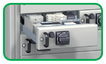
Рис. Schneider ElectricWithdrawn
- The drawer can be fully extracted.
- Allows quick replacement.
- Allows switchboard live change.
- Padlocking is possible on the fixed part.
[Schneider Electric]Отделённое положение
- Выдвижной ящик можно полностью извлечь из шкафа.
- Можно быстро заменить выдвижные ящики.
- Можно заменять ящики, не отключая шкафа.
- Стационарная часть может быть заблокирована навесным замком.
[Перевод Интент]Тематики
- НКУ (шкафы, пульты,...)
Классификация
>>>Синонимы
EN
DE
FR
отсоединенное (изолированное) положение
Положение выдвижной части, при котором в ее главных и вспомогательных цепях достигается изоляционный промежуток, при этом выдвижная часть остается механически присоединенной к НКУ.
Примечание — Изоляционный промежуток может достигаться с помощью специального устройства без механического перемещения выдвижной части.
[ ГОСТ Р 51321. 1-2000 ( МЭК 60439-1-92)]
отсоединенное (изолированное) положение
Положение выдвижной неотделяемой части, при котором в ее главных и вспомогательных цепях на стороне питания обеспечивается изолирующий промежуток, при этом выдвижная неотделяемая часть остается механически соединенной с СНКУ.
Примечание Изолирующий промежуток может быть достигнут с помощью специального устройства без механического перемещения выдвижной неотделяемой части.
[ ГОСТ Р МЭК 61439.2-2012]EN
disconnected position (of a withdrawable part)
isolated position (of a withdrawable part)
the position of a withdrawable part in which an isolating distance or segregation is established in all the circuits of the withdrawable part, that part remaining mechanically attached to the assembly
NOTE – In enclosed high-voltage switchgear and controlgear the auxiliary circuits may not be disconnected.
[IEV number 441-16-28]FR
position de sectionnement (d'une partie débrochable)
position d'une partie débrochable dans laquelle une distance de sectionnement est établie ou un cloisonnement métallique est mis en place dans les circuits de la partie débrochable, cette partie restant mécaniquement reliée à l'ensemble
NOTE – Dans l'appareillage à haute tension sous enveloppe, les circuits auxiliaires peuvent rester branchés.
[IEV number 441-16-28]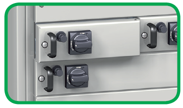
Рис. Schneider Electric
Draw out
- The functional unit is not operational.
- Power and auxiliaries are disconnected.
- Padlocking is possible to keep the drawer in this position.
- Allows maintenance on the process.
[Schneider Electric]Отсоединённое положение
- В данном положении функциональный блок не может выполнять функцию питания нагрузки.
- Главная и вспомогательные цепи отсоединены.
- Ящик можно зафиксировать в данном положении навесным замком.
- Можно выполнять техническое обслуживание.
[Перевод Интент]Тематики
- НКУ (шкафы, пульты,...)
Классификация
>>>Синонимы
EN
- disconnected position (of a withdrawable part)
- draw-out
- draw-out position
- isolated position (of a withdrawable part)
- racked-out position
- withdrawn position
DE
FR
Англо-русский словарь нормативно-технической терминологии > withdrawn position
-
3 co-ordination type 2
- координация типа 2 (пускателя) с устройством защиты от короткого замыкания
координация типа 2 (пускателя) с устройством защиты от короткого замыкания
-Параллельные тексты EN-RU
Co-ordination type 1 and type 2
The co-ordination typologies admitted by the Standard with reference to the behavior of the protection device against short-circuit towards the starter components are classified as “type 1” and “type 2”.
Under short-circuit conditions, the coordination of type “1” allows the contactor and the overload relay to be damaged; as a consequence they could not be able to operate without repairing or replacement of parts. However, the Standard prescribes that these devices do not cause damages to people or installations, for example with parts of the components ejected outside the enclosure.
Under short-circuit conditions, the coordination of type “2” allows the risk of contact welding, provided that the contacts themselves can be easily separated (for example through a screwdriver) without important deformations.
This type of coordination requires that the contactor or the starter do not cause damages to people or installation and that they are able to resume operation after restoring of the standard conditions.
[ABB]Координация типа 1 и 2 с аппаратом защиты от короткого замыкания
Стандарт определяет два типа координации компонентов пускателя с аппаратами защиты от короткого замыкания: тип 1 и тип 2.
Координация типа 1. В условиях короткого замыкания допускается повреждение контактора и теплового реле, в результате чего они могут оказаться непригодными для дальнейшей эксплуатации без ремонта и замены частей. При этом данные устройства не должны создавать опасности для людей и оборудования, например, вследствие вылета частей пускателя из оболочки.
Координация типа 2. В условиях короткого замыкания допускает сваривание контактов при условии, что они могут быть легко разъединены (например, отверткой) без заметной деформации. Контактор или пускатель не должны создавать опасности для людей и оборудования и должны оставаться пригодными для дальнейшей эксплуатации после восстановления нормальных условий.
[Перевод Интент]Тематики
EN
Англо-русский словарь нормативно-технической терминологии > co-ordination type 2
-
4 coordination of type 2
- координация типа 2 (пускателя) с устройством защиты от короткого замыкания
координация типа 2 (пускателя) с устройством защиты от короткого замыкания
-Параллельные тексты EN-RU
Co-ordination type 1 and type 2
The co-ordination typologies admitted by the Standard with reference to the behavior of the protection device against short-circuit towards the starter components are classified as “type 1” and “type 2”.
Under short-circuit conditions, the coordination of type “1” allows the contactor and the overload relay to be damaged; as a consequence they could not be able to operate without repairing or replacement of parts. However, the Standard prescribes that these devices do not cause damages to people or installations, for example with parts of the components ejected outside the enclosure.
Under short-circuit conditions, the coordination of type “2” allows the risk of contact welding, provided that the contacts themselves can be easily separated (for example through a screwdriver) without important deformations.
This type of coordination requires that the contactor or the starter do not cause damages to people or installation and that they are able to resume operation after restoring of the standard conditions.
[ABB]Координация типа 1 и 2 с аппаратом защиты от короткого замыкания
Стандарт определяет два типа координации компонентов пускателя с аппаратами защиты от короткого замыкания: тип 1 и тип 2.
Координация типа 1. В условиях короткого замыкания допускается повреждение контактора и теплового реле, в результате чего они могут оказаться непригодными для дальнейшей эксплуатации без ремонта и замены частей. При этом данные устройства не должны создавать опасности для людей и оборудования, например, вследствие вылета частей пускателя из оболочки.
Координация типа 2. В условиях короткого замыкания допускает сваривание контактов при условии, что они могут быть легко разъединены (например, отверткой) без заметной деформации. Контактор или пускатель не должны создавать опасности для людей и оборудования и должны оставаться пригодными для дальнейшей эксплуатации после восстановления нормальных условий.
[Перевод Интент]Тематики
EN
Англо-русский словарь нормативно-технической терминологии > coordination of type 2
-
5 coordination type 2
- координация типа 2 (пускателя) с устройством защиты от короткого замыкания
координация типа 2 (пускателя) с устройством защиты от короткого замыкания
-Параллельные тексты EN-RU
Co-ordination type 1 and type 2
The co-ordination typologies admitted by the Standard with reference to the behavior of the protection device against short-circuit towards the starter components are classified as “type 1” and “type 2”.
Under short-circuit conditions, the coordination of type “1” allows the contactor and the overload relay to be damaged; as a consequence they could not be able to operate without repairing or replacement of parts. However, the Standard prescribes that these devices do not cause damages to people or installations, for example with parts of the components ejected outside the enclosure.
Under short-circuit conditions, the coordination of type “2” allows the risk of contact welding, provided that the contacts themselves can be easily separated (for example through a screwdriver) without important deformations.
This type of coordination requires that the contactor or the starter do not cause damages to people or installation and that they are able to resume operation after restoring of the standard conditions.
[ABB]Координация типа 1 и 2 с аппаратом защиты от короткого замыкания
Стандарт определяет два типа координации компонентов пускателя с аппаратами защиты от короткого замыкания: тип 1 и тип 2.
Координация типа 1. В условиях короткого замыкания допускается повреждение контактора и теплового реле, в результате чего они могут оказаться непригодными для дальнейшей эксплуатации без ремонта и замены частей. При этом данные устройства не должны создавать опасности для людей и оборудования, например, вследствие вылета частей пускателя из оболочки.
Координация типа 2. В условиях короткого замыкания допускает сваривание контактов при условии, что они могут быть легко разъединены (например, отверткой) без заметной деформации. Контактор или пускатель не должны создавать опасности для людей и оборудования и должны оставаться пригодными для дальнейшей эксплуатации после восстановления нормальных условий.
[Перевод Интент]Тематики
EN
Англо-русский словарь нормативно-технической терминологии > coordination type 2
-
6 type 2 coordination
- координация типа 2 (пускателя) с устройством защиты от короткого замыкания
координация типа 2 (пускателя) с устройством защиты от короткого замыкания
-Параллельные тексты EN-RU
Co-ordination type 1 and type 2
The co-ordination typologies admitted by the Standard with reference to the behavior of the protection device against short-circuit towards the starter components are classified as “type 1” and “type 2”.
Under short-circuit conditions, the coordination of type “1” allows the contactor and the overload relay to be damaged; as a consequence they could not be able to operate without repairing or replacement of parts. However, the Standard prescribes that these devices do not cause damages to people or installations, for example with parts of the components ejected outside the enclosure.
Under short-circuit conditions, the coordination of type “2” allows the risk of contact welding, provided that the contacts themselves can be easily separated (for example through a screwdriver) without important deformations.
This type of coordination requires that the contactor or the starter do not cause damages to people or installation and that they are able to resume operation after restoring of the standard conditions.
[ABB]Координация типа 1 и 2 с аппаратом защиты от короткого замыкания
Стандарт определяет два типа координации компонентов пускателя с аппаратами защиты от короткого замыкания: тип 1 и тип 2.
Координация типа 1. В условиях короткого замыкания допускается повреждение контактора и теплового реле, в результате чего они могут оказаться непригодными для дальнейшей эксплуатации без ремонта и замены частей. При этом данные устройства не должны создавать опасности для людей и оборудования, например, вследствие вылета частей пускателя из оболочки.
Координация типа 2. В условиях короткого замыкания допускает сваривание контактов при условии, что они могут быть легко разъединены (например, отверткой) без заметной деформации. Контактор или пускатель не должны создавать опасности для людей и оборудования и должны оставаться пригодными для дальнейшей эксплуатации после восстановления нормальных условий.
[Перевод Интент]Тематики
EN
Англо-русский словарь нормативно-технической терминологии > type 2 coordination
-
7 removed position (of a removable part)
отделенное положение
Положение съемной или выдвижной части, при котором она находится вне НКУ и механически и электрически отделена от него.
[ ГОСТ Р 51321. 1-2000 ( МЭК 60439-1-92)]
отделенное положение
Положение выдвижной отделяемой части НКУ, когда она находится вне НКУ, механически и электрически отсоединена от него.
[ ГОСТ Р МЭК 61439.1-2013]EN
removed position (of a removable part)
a position of a removable part when it is outside and mechanically and electrically separated from the assembly
[IEV number 441-16-29]FR
position de retrait (d'une partie amovible)
position d'une partie amovible quand elle est retirée et séparée mécaniquement et électriquement de l'ensemble
[IEV number 441-16-29]Параллельные тексты EN-RU
Рис. Schneider ElectricWithdrawn
- The drawer can be fully extracted.
- Allows quick replacement.
- Allows switchboard live change.
- Padlocking is possible on the fixed part.
[Schneider Electric]Отделённое положение
- Выдвижной ящик можно полностью извлечь из шкафа.
- Можно быстро заменить выдвижные ящики.
- Можно заменять ящики, не отключая шкафа.
- Стационарная часть может быть заблокирована навесным замком.
[Перевод Интент]Тематики
- НКУ (шкафы, пульты,...)
Классификация
>>>Синонимы
EN
DE
FR
Англо-русский словарь нормативно-технической терминологии > removed position (of a removable part)
-
8 withdrawn
отделенное положение
Положение съемной или выдвижной части, при котором она находится вне НКУ и механически и электрически отделена от него.
[ ГОСТ Р 51321. 1-2000 ( МЭК 60439-1-92)]
отделенное положение
Положение выдвижной отделяемой части НКУ, когда она находится вне НКУ, механически и электрически отсоединена от него.
[ ГОСТ Р МЭК 61439.1-2013]EN
removed position (of a removable part)
a position of a removable part when it is outside and mechanically and electrically separated from the assembly
[IEV number 441-16-29]FR
position de retrait (d'une partie amovible)
position d'une partie amovible quand elle est retirée et séparée mécaniquement et électriquement de l'ensemble
[IEV number 441-16-29]Параллельные тексты EN-RU
Рис. Schneider ElectricWithdrawn
- The drawer can be fully extracted.
- Allows quick replacement.
- Allows switchboard live change.
- Padlocking is possible on the fixed part.
[Schneider Electric]Отделённое положение
- Выдвижной ящик можно полностью извлечь из шкафа.
- Можно быстро заменить выдвижные ящики.
- Можно заменять ящики, не отключая шкафа.
- Стационарная часть может быть заблокирована навесным замком.
[Перевод Интент]Тематики
- НКУ (шкафы, пульты,...)
Классификация
>>>Синонимы
EN
DE
FR
Англо-русский словарь нормативно-технической терминологии > withdrawn
-
9 co-ordination type 1
- координация типа 1 (пускателя) с устройством защиты от короткого замыкания
координация типа 1 (пускателя) с устройством защиты от короткого замыкания
-Параллельные тексты EN-RU
Co-ordination type 1 and type 2
The co-ordination typologies admitted by the Standard with reference to the behavior of the protection device against short-circuit towards the starter components are classified as “type 1” and “type 2”.
Under short-circuit conditions, the coordination of type “1” allows the contactor and the overload relay to be damaged; as a consequence they could not be able to operate without repairing or replacement of parts. However, the Standard prescribes that these devices do not cause damages to people or installations, for example with parts of the components ejected outside the enclosure.
[ABB]Координация типа 1 и 2 с аппаратом защиты от короткого замыкания
Стандарт определяет два типа координации компонентов пускателя с аппаратами защиты от короткого замыкания: тип 1 и тип 2.
Координация типа 1. В условиях короткого замыкания допускается повреждение контактора и теплового реле, в результате чего они могут оказаться непригодными для дальнейшей эксплуатации без ремонта и замены частей. При этом данные устройства не должны создавать опасности для людей и оборудования, например, вследствие вылета частей пускателя из оболочки.
[Перевод Интент]Тематики
EN
Англо-русский словарь нормативно-технической терминологии > co-ordination type 1
-
10 coordination of type 1
- координация типа 1 (пускателя) с устройством защиты от короткого замыкания
координация типа 1 (пускателя) с устройством защиты от короткого замыкания
-Параллельные тексты EN-RU
Co-ordination type 1 and type 2
The co-ordination typologies admitted by the Standard with reference to the behavior of the protection device against short-circuit towards the starter components are classified as “type 1” and “type 2”.
Under short-circuit conditions, the coordination of type “1” allows the contactor and the overload relay to be damaged; as a consequence they could not be able to operate without repairing or replacement of parts. However, the Standard prescribes that these devices do not cause damages to people or installations, for example with parts of the components ejected outside the enclosure.
[ABB]Координация типа 1 и 2 с аппаратом защиты от короткого замыкания
Стандарт определяет два типа координации компонентов пускателя с аппаратами защиты от короткого замыкания: тип 1 и тип 2.
Координация типа 1. В условиях короткого замыкания допускается повреждение контактора и теплового реле, в результате чего они могут оказаться непригодными для дальнейшей эксплуатации без ремонта и замены частей. При этом данные устройства не должны создавать опасности для людей и оборудования, например, вследствие вылета частей пускателя из оболочки.
[Перевод Интент]Тематики
EN
Англо-русский словарь нормативно-технической терминологии > coordination of type 1
-
11 coordination type 1
- координация типа 1 (пускателя) с устройством защиты от короткого замыкания
координация типа 1 (пускателя) с устройством защиты от короткого замыкания
-Параллельные тексты EN-RU
Co-ordination type 1 and type 2
The co-ordination typologies admitted by the Standard with reference to the behavior of the protection device against short-circuit towards the starter components are classified as “type 1” and “type 2”.
Under short-circuit conditions, the coordination of type “1” allows the contactor and the overload relay to be damaged; as a consequence they could not be able to operate without repairing or replacement of parts. However, the Standard prescribes that these devices do not cause damages to people or installations, for example with parts of the components ejected outside the enclosure.
[ABB]Координация типа 1 и 2 с аппаратом защиты от короткого замыкания
Стандарт определяет два типа координации компонентов пускателя с аппаратами защиты от короткого замыкания: тип 1 и тип 2.
Координация типа 1. В условиях короткого замыкания допускается повреждение контактора и теплового реле, в результате чего они могут оказаться непригодными для дальнейшей эксплуатации без ремонта и замены частей. При этом данные устройства не должны создавать опасности для людей и оборудования, например, вследствие вылета частей пускателя из оболочки.
[Перевод Интент]Тематики
EN
Англо-русский словарь нормативно-технической терминологии > coordination type 1
-
12 type 1 coordination
- координация типа 1 (пускателя) с устройством защиты от короткого замыкания
координация типа 1 (пускателя) с устройством защиты от короткого замыкания
-Параллельные тексты EN-RU
Co-ordination type 1 and type 2
The co-ordination typologies admitted by the Standard with reference to the behavior of the protection device against short-circuit towards the starter components are classified as “type 1” and “type 2”.
Under short-circuit conditions, the coordination of type “1” allows the contactor and the overload relay to be damaged; as a consequence they could not be able to operate without repairing or replacement of parts. However, the Standard prescribes that these devices do not cause damages to people or installations, for example with parts of the components ejected outside the enclosure.
[ABB]Координация типа 1 и 2 с аппаратом защиты от короткого замыкания
Стандарт определяет два типа координации компонентов пускателя с аппаратами защиты от короткого замыкания: тип 1 и тип 2.
Координация типа 1. В условиях короткого замыкания допускается повреждение контактора и теплового реле, в результате чего они могут оказаться непригодными для дальнейшей эксплуатации без ремонта и замены частей. При этом данные устройства не должны создавать опасности для людей и оборудования, например, вследствие вылета частей пускателя из оболочки.
[Перевод Интент]Тематики
EN
Англо-русский словарь нормативно-технической терминологии > type 1 coordination
-
13 parallel UPS system
параллельная система ИБП
-
[Интент]Parallel Operation: The system shall have the option to install up to four (4) UPSs in parallel configuration for redundancy or capacity.
1. The parallel UPS system shall be of the same design, voltage, and frequency. UPS modules of different size ratings shall be permitted to be paralleled together for purposes of increased capacity or UPS module redundancy. The UPSs in the parallel configuration shall not be required to have the same load capacity rating.
2. Parallel Capacity: With N+0 system-level redundancy, up to 2MW of load can be supported by the system.
3. Parallel Redundancy: With N+1 system-level redundancy, up to 1.5MW of load can be supported by the system, and only the UPS being replaced must be isolated from the source (bypass operation is not required for the entire system during the UPS replacement procedure).
4. Output control: A load sharing circuit shall be incorporated into the parallel control circuits to ensure that under no-load conditions, no circulating current exists between modules. This feature also allows each UPS to share equal amounts of the total critical load bus. The output voltage, output frequency, output phase angle, and output impedance of each module shall operate in uniformity to ensure correct load sharing. This control function shall not require any additional footprint and shall be an integral function of each UPS. The static bypass switches shall be connected in parallel.
5. Parallel System Controls: To avoid single points of failure, the UPS system shall have no single dedicated control system designed to control the operation of the parallel UPS system. Control of and direction of parallel UPSs shall take place via a master/slave relationship, where the first UPS to receive logic power asserts itself as a master. In the event of a master failure, a slave UPS shall take the role of master and assume the responsibility of the previous master UPS. Regardless of which UPS is master or slave, user changes to the system status, such as request for bypass, can be done from any UPS connected to the bus and all UPS on the bus shall transfer in simultaneously.
6. Communication: Communication between modules shall be connected so that the removal of any single cable shall not jeopardize the integrity of the parallel communication system. Load sharing communications shall be galvanically isolated for purposes of fault tolerance between UPS modules. A UPS module's influence over load sharing shall be inhibited in any mode where the UPS inverter is not supporting its output bus. Transfers to and from bypass can be initiated from any online UPS in the system.
7. Display: Each UPS multi-color LCD touch screen user interface shall be capable of using an active touch screen mimic bus to show the quantity of UPS(s) connected to the critical bus, as well as the general status of each UPS, such as circuit breaker status information. Any touchscreen display shall support the configuration of the [entire parallel] system and shall provide event and alarm data for all UPSs in the parallel configuration. A Virtual Display Application shall be available for download to the customer’s computer and shalll support remote monitoring of a complete system with up to 4 UPSs in parallel.
8. Battery runtime: Each UPS must have its own battery solution. The battery solution for the entire system can be a combination of standard and third-party batteries, but each UPS must use only one battery solution – either standard or third-party batteries.
9. Switchgear: A custom switchgear option shall be required for parallel operation.
[Schneider Electric]Тематики
EN
Англо-русский словарь нормативно-технической терминологии > parallel UPS system
См. также в других словарях:
Replacement windows — “Replacement windows” usually refer to new windows that mount within the frame of the existing wood window. They are typically made without a structural frame; instead, they rely on the strength of the original window for support.Replacement… … Wikipedia
Local replacement algorithm — With multiple processes competing for frames, we can classify page replacement algorithms into two broad categories:global replacement and local replacement.Global replacement allows a process to select a replacement frame from the set of all… … Wikipedia
Eastern span replacement of the San Francisco — San Francisco – Oakland Bay Bridge (eastern span replacement) Artistic rendition of the new eastern span of the Bay Bridge seen from Treasure Island (ca. 2014) Official name To be determ … Wikipedia
Desktop replacement computer — A desktop replacement Acer 8920 laptop with an 18.4 inch screen which can replace a desktop with its big screen. A desktop replacement computer (DTR) is a personal computer that provides the full capabilities of a desktop computer while remaining … Wikipedia
Orbital replacement unit — Orbital Replacement Units (ORUs) are key elements of the International Space Station that can be readily replaced when the unit either passes its design life or fails. Examples of ORUs are: pumps, storage tanks, controller boxes, antennas, and… … Wikipedia
Axiom schema of replacement — In set theory, the axiom schema of replacement is a schema of axioms in Zermelo Fraenkel set theory (ZFC) that asserts that the image of any set under any definable mapping is also a set. It is necessary for the construction of certain infinite… … Wikipedia
Knee replacement — Knee replacement, or knee arthroplasty, is a common surgical procedure most often performed to relieve the pain and disability from degenerative arthritis, most commonly osteoarthritis, but other arthritides as well. [ cite… … Wikipedia
Value over replacement player — In baseball, value over replacement player (or VORP) is a statistic invented by Keith Woolner that demonstrates how much a hitter contributes offensively or how much a pitcher contributes to his team in comparison to a fictitious replacement… … Wikipedia
Aortic valve replacement — is a cardiac surgery procedure in which a patient s aortic valve is replaced by a different valve. The aortic valve can be affected by a range of diseases; the valve can either become leaky (aortic insufficiency / regurgitation) or partially… … Wikipedia
Medium Tactical Vehicle Replacement — Two MK23 MTVR s equipped with Plasan MAS armor at Camp Pendleton, California … Wikipedia
Multiple isomorphous replacement — or MIR is the most common approach of solving the phase problem in X ray crystallography. This method is conducted by soaking the crystal of a sample to be analyzed with a heavy atom solution or co crystallization with the heavy atom. The… … Wikipedia